Network topology and switch configurations as shown below:
Hint:
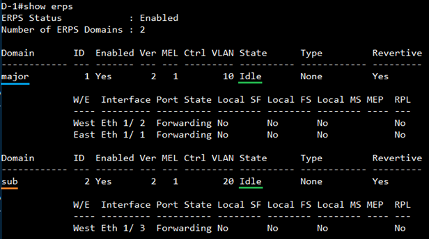
The connections (blue line) between the switch A, B, C, D belong to ERPS major-ring.
The connections (orange line) between the switch C, D, E, F belong to ERPS sub-ring.

Major Ring (Domain): Switch A is RPL Owner for major ring.

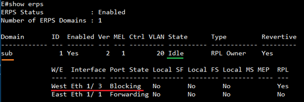
Sub Ring (Domain): Switch E is RPL Owner for sub ring.

Blocking port

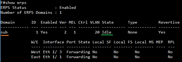
Default Status
A

B

C

D
E
F
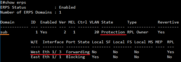
If there is a link failure in sub-ring, the state of blocking port of sub-ring may change from blocking to forwarding.
Hint: The connections (orange line) between the switch C, D, E, F belong to ERPS sub-ring.
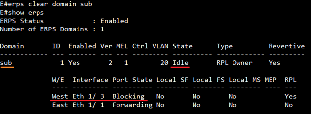
For example: The link between switch C and E is disconnected. The port 3 of switch E (RPL-Owner for sub-ring) will change state from blocking to forwarding.

Meanwhile, the state of Sub-Domain will change from Idle to Protection.
If there is a link failure in major-ring, the status of sub-ring will not change.
Hint:
The connections (blue line) between the switch A, B, C, D belong to ERPS major-ring.

For example: Links between switch C and D, Switch B and D) are disconnected, but blocking port of sub-ring is still at blocking state. The state of sub-ring is still “Idle”.
The status of Sub-Domain does not change. And port 3 of switch E is still blocking.
Next Page How to get the ARP and MAC address table via SNMP on Edgecore switch ?
